No products in the cart.
The tool typically selected for measuring surface magnetism is a gaussmeter, also known as a teslameter.
The operating principle of a gaussmeter is primarily based on the Hall effect: when a current-carrying conductor is placed within a magnetic field, the action of the Lorentz force induces a transverse potential difference in a direction perpendicular to both the magnetic field and the current. A gaussmeter is an instrument designed to measure magnetic fields based on this very principle of the Hall effect; within a magnetic field, a Hall probe generates a "Hall voltage" due to the Hall effect, and the measuring instrument then calculates the magnetic field strength value based on this Hall voltage and a known Hall coefficient.
Most modern Gaussmeters are typically equipped with unidirectional Hall probes—meaning they can measure magnetic field strength in only one direction: specifically, the direction perpendicular to the Hall chip. In certain high-end measurement applications, however, Hall probes capable of measuring three-dimensional magnetic fields are available; through internal calculations performed by the instrument, these probes can simultaneously display magnetic field strengths along the X, Y, and Z axes, and utilize trigonometric functions to derive the maximum magnetic field strength.
Gaussmeters are generally capable of measuring both DC and AC magnetic fields. The display units can typically be toggled between Gaussian units (Gs) and International System (SI) units (mT); among these capabilities, the measurement of DC magnetic fields is the most widely utilized application within the industry.
To measure magnetic fields in real-time, the "REAL" function must be selected; the display screen will then show the instantaneous magnetic field value and its polarity.
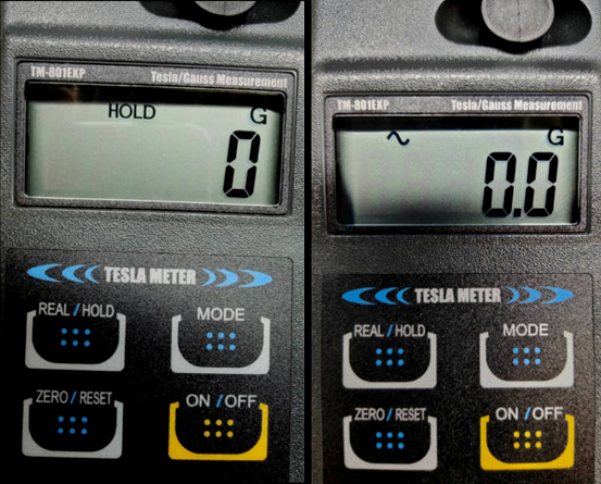
When it is necessary to capture the peak magnetic field value—along with its corresponding polarity—during a measurement session, the "HOLD" function should be employed.
As illustrated in the figure below, the display screen will indicate "HOLD"; the displayed numerical value and polarity represent the captured peak magnetic field and its associated polarity. If no such indicator is present, the device is operating in "REAL" mode. Additionally, pressing the "MODE" button allows the user to switch to the AC magnetic field measurement mode, as indicated by the appearance of the "~" symbol on the screen (as shown in the figure below).
Precautions for Using a Gaussmeter:
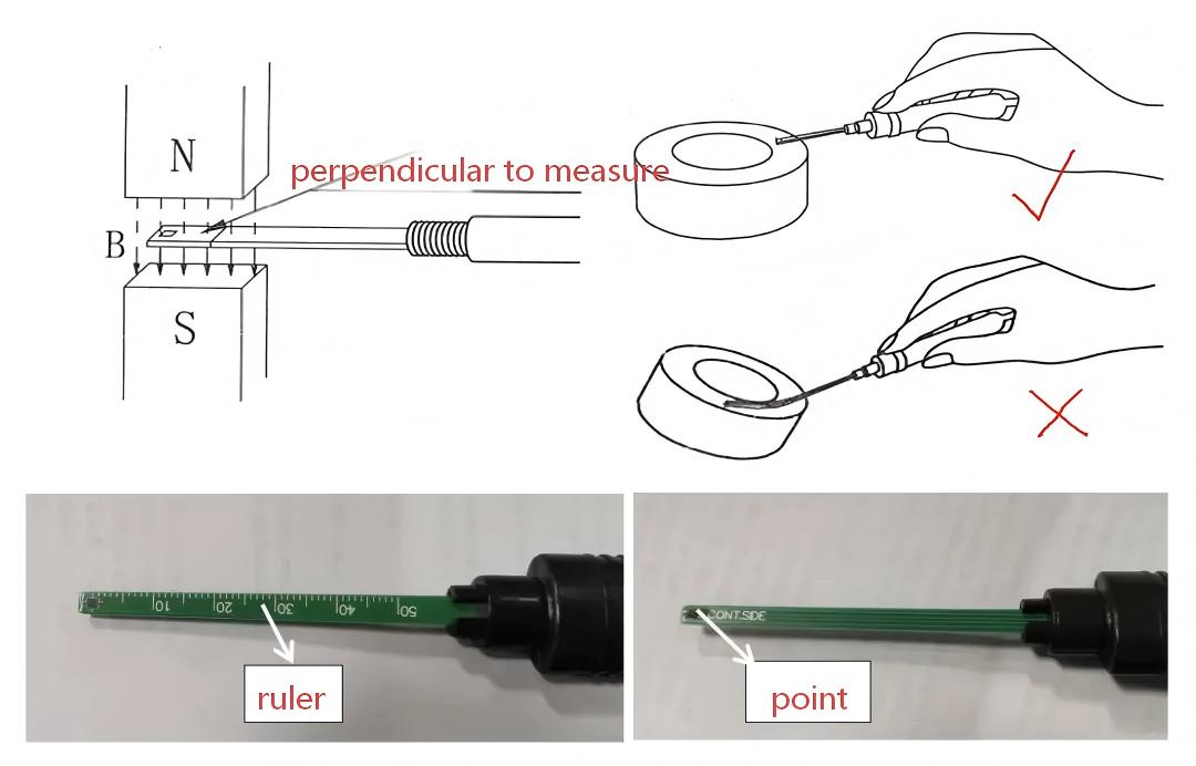
1.When using a Gaussmeter to measure surface magnetism, never excessively bend the probe. The Hall sensor chip located at the tip should generally be placed in light contact—under gentle pressure—against the surface of the magnet. This serves two purposes: first, to ensure the measurement point remains fixed; and second, to ensure the probe sits flush against the measurement surface. Furthermore, the probe must be held level relative to the measurement surface; however, under no circumstances should it be pressed down with excessive force.
2.The Hall sensor chip is capable of detecting magnetic fields on both of its sides; however, the resulting numerical readings and polarity indications will differ depending on which side is used. The side marked with a scale is intended solely for the convenient identification and positioning of the measurement point; it must *not* be used as the actual measurement surface. The side *without* the scale is the designated measurement surface.
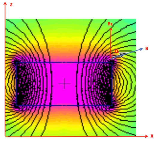
Gaussmeters typically measure the magnetic field strength Bz perpendicular to the measurement plane by default. The figure below displays a simulation of a standard magnet magnetized along the Z-axis. As is evident, the magnetic field is a vector quantity, and the magnetic field strength along the Z-axis can be denoted as Bz. Since the magnetic flux paths are shortest at the corners, the magnetic flux lines are more concentrated in those regions; consequently, the overall magnetic field strength B is stronger at the corners than at the center. However, the Z-axis component Bz is not necessarily stronger at the corners than at the center in every instance. Due to the spatial limitations inherent in the sensing area of the Hall effect chip used for measurement, the magnetic field strength measured at the corners is generally observed to be stronger than that at the center—or, at the very least, it will not be lower than the field strength at the center.
It is particularly important to note here that when the direction of magnetization varies—even on the exact same measurement surface—the measured values can differ significantly.
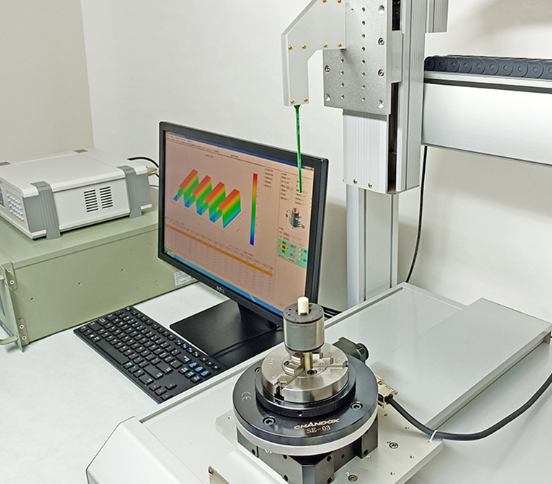
For applications requiring dynamic measurements, or where the magnetic fields at various measurement points must be fitted into a waveform curve, a magnetic field scanner is required. Such a device relies on either single-axis or three-axis Hall sensors to perform measurements; by utilizing a designed scanning trajectory and data acquisition system, it subsequently generates and outputs the magnetic field measurement curve.