No products in the cart.
Surface flux density is a critical technical parameter for finished magnets. As the name implies, it refers to the magnetic induction strength at the surface; within the industry, it is also colloquially referred to as "surface magnetic field strength"—or simply "surface field." In applications that rely on the ambient magnetic field, the surface flux density—or the magnetic induction value at a specific designated point—is typically stipulated as a key technical requirement. It is important to clarify at the outset that surface flux density is a directional quantity; specifically, the value we typically cite refers to the component perpendicular to the pole face.
Can surface flux density be calculated?
If so, how is it calculated?
This is a question of considerable interest to many. While various calculation formulas can be found online—and indeed, many magnet manufacturers provide corresponding calculation tools on their websites for user convenience—anyone who has utilized these resources will have noticed a limitation: these formulas and tools are generally capable of calculating the surface flux density only for cylindrical and rectangular magnets, and specifically, only for the *center* of the surface. Does this imply that calculating surface flux density for other shapes is inherently difficult? Is it equally difficult to determine the *maximum* surface flux density? The answer is yes: accurately calculating surface flux density is, in reality, an extremely difficult and complex undertaking. For cylindrical and rectangular magnets, we typically make certain default assumptions: that the magnetic field distribution is ideal and symmetrical; that the surface flux density at the center is ideally perpendicular to the pole face; and that the magnetic permeability of both the air gap and the magnet itself are equal to 1.0. It is only by basing calculations on these specific conditions that relatively simple calculation methods become feasible—such as the formulas provided by TDK:
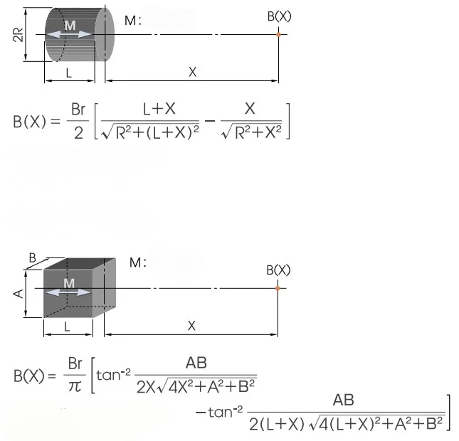
Based on the formulas mentioned above, one can create an Excel calculator to facilitate calculations—a method that serves as the source for the calculation programs found on many websites. However, in actual practice, users often find that the accuracy of the results appears insufficient; for some products, the calculated values diverge significantly from the measured values. Take, for example, an N50 magnet measuring 10x10mm. When measuring the magnetic field at the exact center of the pole face using a Gaussmeter—assuming the probe is in direct contact with the magnet surface with no air gap, and excluding any potential instrument error—if we apply the formula using a residual induction (Br) value of 14 kGs, the calculated surface field strength at the center should theoretically be 6261 Gs. Yet, in reality, no matter how you perform the measurement, it is impossible to achieve this specific value—you would not even reach this figure using an N54 grade magnet. What accounts for this discrepancy? Could it be that even TDK's formulas are inaccurate?
To analyze this issue, we must first understand the underlying basis upon which these formulas were established, rather than simply adopting them blindly. First, the variable "X" in the formula represents the distance from the calculation point to the surface of the magnet. Although we typically place the probe directly against the magnet's surface during measurement, the Gaussmeter probe itself does not leave the Hall sensor chip exposed; instead, it is encased within a protective housing. For instance, with the Japanese-made KANETEC Gaussmeters—widely used throughout the industry—the Hall sensor chip within the probe is covered by a transparent protective layer approximately 0.2mm thick. Furthermore, with sufficient measurement experience, one will notice a distinct difference between the surface field strength of "raw" magnet blocks and that of finished products. Why is this? It is due to the influence of the surface plating applied to the finished product. For example, with Nickel-Copper-Nickel (Ni-Cu-Ni) plating, the thickness on a single side is typically 0.02mm; moreover, since nickel itself is a ferromagnetic material, it creates a shielding effect on the magnetic field, thereby causing a reduction in the measured values. Additionally—as we have consistently emphasized—the surface field strength measured by a Gaussmeter does not represent a single, ideal point, but rather a small localized area. Furthermore, the actual degree of orientation and uniformity within a real-world magnet can never be absolutely perfect. Therefore, based on these inherent limitations and extensive practical experience, it is advisable to apply an additional compensation of 0.4–0.5mm to the "X" value: specifically, a compensation of 0.5mm is recommended when the Pc value is below 3, and a compensation of 0.4mm when the Pc value is 3 or higher.
The foregoing explains the compensation applied to the X-value. However, there is an even more critical point to consider: the validity of the formula is predicated on the assumption that the magnetic permeability of both the magnet and the air gap is exactly 1.0. While we know that the permeability of air—at 1.000065—is indeed very close to 1.0, the permeability of the magnet itself is far less ideal; in practice, a value of 1.02 is already considered excellent. Most N-series and M-series NdFeB magnets actually exceed 1.05, with some even reaching 1.1. Why, then, does magnetic permeability influence the test data? To analyze and understand this phenomenon, we must return to the demagnetization curve.
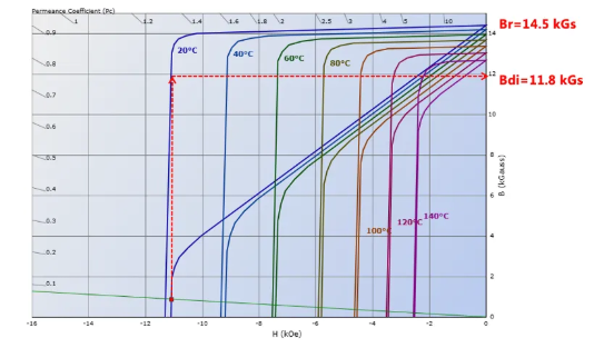
As can be observed from the demagnetization curve, the actual residual induction of a magnet in an open-circuit state does not correspond to the ideal theoretical value of Br; rather, it is lower than Br. We refer to this actual value as the intrinsic flux density (Bdi). The reason for this discrepancy lies in the fact that the initial segment of the blue J-H demagnetization curve is not ideally parallel to the X-axis, but is instead inclined. Consequently, the numerical value of Br is necessarily greater than that of Hcb, meaning that the recoil permeability—calculated as μrec = Br/Hcb—cannot equal 1.0. A second scenario arises when the B-H curve exhibits a "knee point," and the magnet's operating point falls below this knee point. In such cases, the actual Bdi value will be significantly lower than Br, causing calculated results to deviate substantially from actual measured values—as illustrated in the figure below. This phenomenon also explains why the actual surface flux density at the center of an N54 magnet (measuring 20 × 10 × 1 mm) is not only far lower than the theoretically calculated value but is also highly unstable.
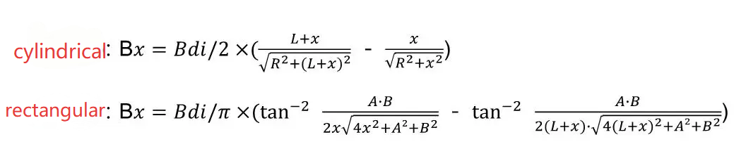
Based on the above, modifying the formula by substituting *Br* with *Bdi*—and applying appropriate compensation for *X*—yields a relatively accurate calculation method. However, in practice, *Bdi* is often difficult to determine precisely. The ideal approach involves calculating it graphically based on the actual demagnetization curve and the *Pc* value; yet, this method is quite cumbersome. Therefore, it is recommended that users perform the calculation according to the following guidelines:
1. First and foremost, the operating point must be situated *above* the knee point of the B-H demagnetization curve, while maintaining an adequate safety margin. Particular attention should be paid to N-grade materials with a maximum energy product exceeding 45 MGOe, as well as thin magnets with a *Pc* value of less than 0.6. If the operating point falls *below* the knee point, the magnetic properties become unstable; even if one attempts to estimate the central surface flux density by extrapolating *Bdi* from the curve, the resulting fluctuations will be significant. Consequently, it becomes necessary to increase the intrinsic coercivity (*Hcj*) to ensure the operating point remains above the knee point—or, ideally, to ensure that the B-H curve exhibits no knee point whatsoever.
2. Provided that the condition outlined in Point 1 is satisfied, *Bdi* can be calculated using the formula: *Bdi* = Br × (Pc + 1) / (μrec + Pc). The value of *μrec* (recoil permeability) should be determined based on actual material specifications; generally, it falls within the range of 1.08–1.1 for grades below N40; 1.06–1.08 for N40 and above; 1.05–1.06 for M-grade materials; 1.04 for H-grade materials; and 1.03 for other grades.
Ultimately, the formulas for calculating the central surface flux density of cylindrical (or near-cylindrical) magnets and rectangular (or near-rectangular) magnets are as follows:
Note: The formulas above are applicable only to permanent magnets with linear demagnetization curves—such as NdFeB, SmCo, and ferrite magnets. They are not suitable for calculating surface magnetic flux density in magnets with non-linear demagnetization curves—such as AlNiCo, FeCrCo, and various soft magnetic materials. Furthermore, this method is inapplicable to magnets with skewed orientation, where the direction of magnetization is not perpendicular to the plane of the magnetic poles.