No products in the cart.
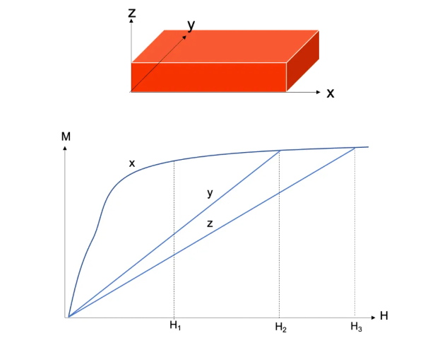
When permanent magnets are fabricated into specific shapes—taking the block-shaped magnet illustrated below as an example—measurements of the open-circuit magnetization curves along the x, y, and z axes reveal a distinct phenomenon: magnetization along the x-direction requires only a relatively low magnetic field (H1) to reach technical saturation, whereas measurements along the y- and z-directions require significantly stronger magnetic fields to achieve the same level of saturation. This phenomenon is termed *shape anisotropy* in permanent magnets. The direction requiring the lowest magnetic field to reach technical saturation is designated the *easy axis of magnetization*, while the direction requiring the highest magnetic field to reach technical saturation is designated the *hard axis of magnetization*.
Demagnetizing Field (Hd)
Why do permanent magnets of specific shapes (i.e., non-spherical shapes) exhibit the phenomenon of shape anisotropy? This is attributed to the presence of a demagnetizing field within non-ring-shaped permanent magnets.
We know that block-shaped or cylindrical permanent magnets invariably possess distinct North (N) and South (S) poles; the very existence of these magnetic poles generates a magnetic field both in the surrounding space and within the magnet itself. The magnetic field generated by the poles of a permanent magnet always flows from the N pole to the S pole—a directional flow that holds true for both the external environment and the magnet's interior. The internal demagnetizing field of a permanent magnet is denoted as Hd; its direction runs from the N pole to the S pole, whereas the direction of the magnet's magnetic moment (Mm)—or its magnetization vector—runs from the S pole to the N pole. Since the internal field Hd opposes the direction of the magnetization vector M, it exerts a demagnetizing influence; hence, it is termed the "demagnetizing field."
How, then, is the demagnetizing field of a permanent magnet generated? We can conceptualize a permanent magnet as being composed of two constituent magnets, A and B. Magnet A is situated precisely within the magnetic field generated by Magnet B, and conversely, Magnet B is situated within the magnetic field generated by Magnet A. These generated fields flow specifically from the N pole to the S pole; consequently, their direction is diametrically opposed to the direction of the magnet's overall magnetization vector—which is why they are designated as demagnetizing fields.
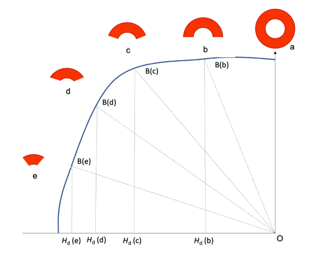
The intensity of a permanent magnet's demagnetizing field is contingent upon the magnet's specific shape and dimensions. Consider, for instance, a ring-shaped permanent magnet: the intensity of its demagnetizing field varies in accordance with the size of the gap in the ring (which effectively corresponds to the magnet's length). When such a ring-shaped magnet is magnetized along the direction of its central axis, no demagnetizing field is generated. However, if the ring-shaped magnet is severed in half, the resulting semi-circular segment will possess a demagnetizing field denoted as Hd. Furthermore, as the ring-shaped magnet is cut into progressively shorter segments, the absolute magnitude of its demagnetizing field (Hd) increases correspondingly. The sequence of this gradual increase in the absolute magnitude of the demagnetizing field can be expressed as: Hd (e) > Hd (d) > Hd (c) > Hd (b) > Hd (a) → 0.
From this, we can deduce the following: if a permanent magnet possesses insufficient intrinsic coercivity (Hcj)—and is fabricated in a relatively thin configuration—attempting to magnetize it along its thin dimension may prove unsuccessful, as the magnitude of the demagnetizing field generated within it becomes excessively large.
Demagnetization Factor N
The example above illustrates that the magnitude of a permanent magnet's demagnetizing field is related to the magnet's shape and dimensional ratio. Both experimental results and theoretical calculations demonstrate that the demagnetizing field of a permanent magnet is given by Hd = NM, where M represents the magnetization of the permanent magnet and N is the demagnetization factor; the negative sign in the equation indicates that the direction of Hd is opposite to that of M.
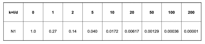
For an infinitely long cylindrical permanent magnet, the demagnetization factor along the longitudinal direction N1 and the demagnetization factor along the diametral direction Nd can be expressed by the following equations, where k is the dimensional factor k = l/d, d is the diameter of the cylindrical magnet, and l is its length.
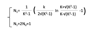
For any permanent magnet, the sum of the demagnetization factors in three mutually perpendicular directions (N1 + Nd + Nd1 = 1) equals 1.0. It can be observed that when k = l/d = 0 (corresponding to an extremely thin plate), the demagnetization factor approaches N1 to 1.0. For a cylindrical permanent magnet magnetized axially, the variation of the demagnetization factor along the length l is illustrated in the figure below. When the length l is approximately 200 times the diameter, the demagnetization factor becomes negligible, and the demagnetizing field can effectively be disregarded.