Custom NdFeB block magnets manufactured to your required length, width, thickness, grade, coating, magnetization direction, tolerance and application requirements.
From engineering samples and custom prototypes to volume OEM production.
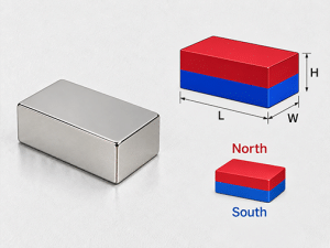
Block magnets can be customized around the dimensional, magnetic, thermal and environmental requirements of your application. Send us a drawing, target specifications or application requirements for engineering review.
Custom dimensions based on your drawing and assembly space.
NdFeB grades selected around magnetic and temperature requirements.
Br, Hcb, Hcj and BHmax requirements can be reviewed
Magnetization through thickness, length, width or other specified direction.
Nickel, zinc, epoxy and other finishes for different environments.
Critical dimensional tolerances based on fit and assembly requirements.
Material selection based on continuous and peak operating temperature.
Engineering samples, trial orders and volume production requirements.
A custom block magnet is typically defined by its length, width and thickness. These dimensions influence assembly fit, magnetic volume, pole-face area and the resulting magnetic field in the application.
When preparing a drawing, identify the dimensions that are critical to fit or magnetic performance. Edge details, chamfers, flatness and other geometric requirements can also be reviewed according to the application and manufacturing process.
| Design Parameter | Custom Options |
|---|---|
| Length (L) | Made to drawing or specified dimensions |
| Width (W) | Made to drawing or specified dimensions |
| Thickness (T) | Made to drawing or specified dimensions |
| Edge / Chamfer | Evaluated according to geometry and assembly requirements |
| Flatness / Parallelism | Specify when critical to the application |
| Dimensional Tolerance | Defined according to critical dimensions |
| Units | Inch or metric drawings accepted |
The longest dimension of the rectangular magnet.
The second planar dimension of the block.
The distance between the two large flat faces when the magnet is designed for through-thickness magnetization.
The dimension names alone do not define the magnetization direction. Always specify which faces should form the north and south poles.
Magnetization direction is a critical specification for block magnets because the same dimensions can produce very different field orientations depending on which axis is magnetized.
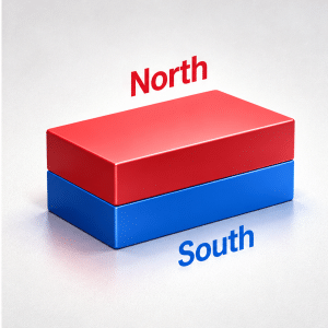
The north and south poles are located on the two opposite faces across the thickness dimension.
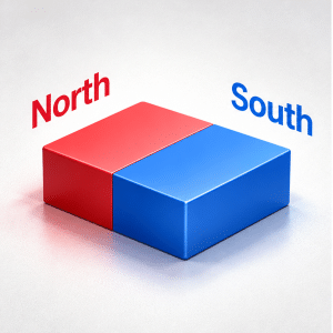
The magnet is magnetized along its length, placing the poles on the two opposite end faces.
| Drawing Requirement | Example |
|---|---|
| Magnet Dimensions | L × W × T |
| Magnetization Axis | Through length, width or thickness |
| North Pole Face | Identify on the drawing when orientation matters |
| Pole Pattern | Two-pole or specified special configuration |
| Assembly Orientation | Show mating steel, sensor or adjacent magnets when relevant |
Magnet grade should be selected according to the required magnetic output, geometry, operating temperature and resistance to demagnetization rather than grade number alone.
N35 | N38 | N40 | N42 | N45 | N48 | N50 | N52
| Property | Symbol | What It Defines |
|---|---|---|
| Remanence | Br | Magnetic flux density retained after magnetization |
| Coercive Force | Hcb | Resistance to an external reverse magnetic field |
| Intrinsic Coercivity | Hcj | Resistance to irreversible demagnetization |
| Maximum Energy Product | (BH)max | Magnetic energy density capability |
| Maximum Operating Temperature | — | Temperature limit considered for the application |
Grade alone does not determine the magnetic field or holding force of the finished component. Block dimensions, magnetization direction, working air gap, mating steel and the surrounding magnetic circuit can all affect application performance.
Two block magnets made from the same NdFeB grade can perform differently when their length, width, thickness or magnetization direction changes. The geometry determines magnetic volume, pole-face area and the field distribution available to the assembly.
| Coating | Typical Consideration |
|---|---|
| Ni-Cu-Ni | Common protective finish for general industrial applications |
| Zinc | Alternative metallic finish for suitable operating environments |
| Epoxy | Considered where additional corrosion resistance is required |
| Other Finishes | Evaluated according to application and environment |
Coating selection should be based on humidity, corrosion exposure, handling conditions, assembly method and the expected operating environment.
Operating temperature can influence both grade selection and long-term magnetic stability. When requesting a custom block magnet, provide the normal operating temperature as well as any short-term peak temperature the component may experience.
Normal temperature during long-term operation.
Highest short-duration temperature the magnet may experience.
Reverse magnetic fields, elevated temperature and magnetic circuit conditions should be identified when relevant
High-temperature NdFeB grades can be evaluated according to project requirements.
Operating temperature can influence both grade selection and long-term magnetic stability. When requesting a custom block magnet, provide the normal operating temperature as well as any short-term peak temperature the component may experience.
Normal temperature during long-term operation.
Highest short-duration temperature the magnet may experience.
Reverse magnetic fields, elevated temperature and magnetic circuit conditions should be identified when relevant.
High-temperature NdFeB grades can be evaluated according to project requirements.
Block magnets are commonly produced from sintered NdFeB material and finished to final dimensions through secondary machining and grinding processes. Critical dimensions should be identified on the drawing so tolerance requirements can be evaluated appropriately.
| Requirement | What to Specify |
|---|---|
| Length Tolerance | Identify when critical to fit |
| Width Tolerance | Identify when critical to assembly |
| Thickness Tolerance | Important where air gap or stack height is controlled |
| Flatness | Specify when required |
| Parallelism | Specify where mating surfaces are critical |
| Edge / Chamfer | Include on drawing when required |
| Surface Condition | Define special inspection requirements if applicable |