Every magnet datasheet carries one headline number — pull force: 130 kgf — and almost every buyer has learned, sooner or later, that the magnet in their hand does not behave like that number. The part holds a third of it when the load slides sideways, a half of it when the steel is painted, and less than a quarter of it once the application combines those conditions. None of that means the datasheet lied. It means neodymium magnet pull force is a laboratory measurement under four perfect conditions, and the application never offers perfect conditions. Understanding what the number does and does not promise is the difference between a magnet that holds for years and one that lets go in the first week.
This guide is the bridge between the number on the box and the force you actually get. We cover what pull force measurably is, why shear force is roughly one third of it, the five factors that move the real figure up or down, and a worked example that takes a 130 kgf pot magnet down to the 25 kgf it honestly delivers in the field. By the end, the rule for sizing a magnet will be arithmetic instead of hope — the same arithmetic our engineering team applies to every holding application we quote.
Pull force — also called holding force, breakaway force or max pull — is defined by a test, and the test is worth reading carefully because every clause is a condition your application may not satisfy. The neodymium magnet pull force you buy is only as good as these four clauses:
A neodymium magnet pull force figure is the force needed to separate the magnet from that ideal steel, measured slowly at the moment of breakaway. The magnetization, the geometry and the steel circuit all contribute — which is why a pot magnet with a steel cup shows several times the pull of the bare disc inside it: the cup is part of the measurement, not packaging.
Change any one of the four conditions and the real force changes. Change two, and it changes more than you would expect from adding the two effects — the losses multiply rather than sum. That is why two magnets with an identical neodymium magnet pull force rating can behave completely differently in two workshops.
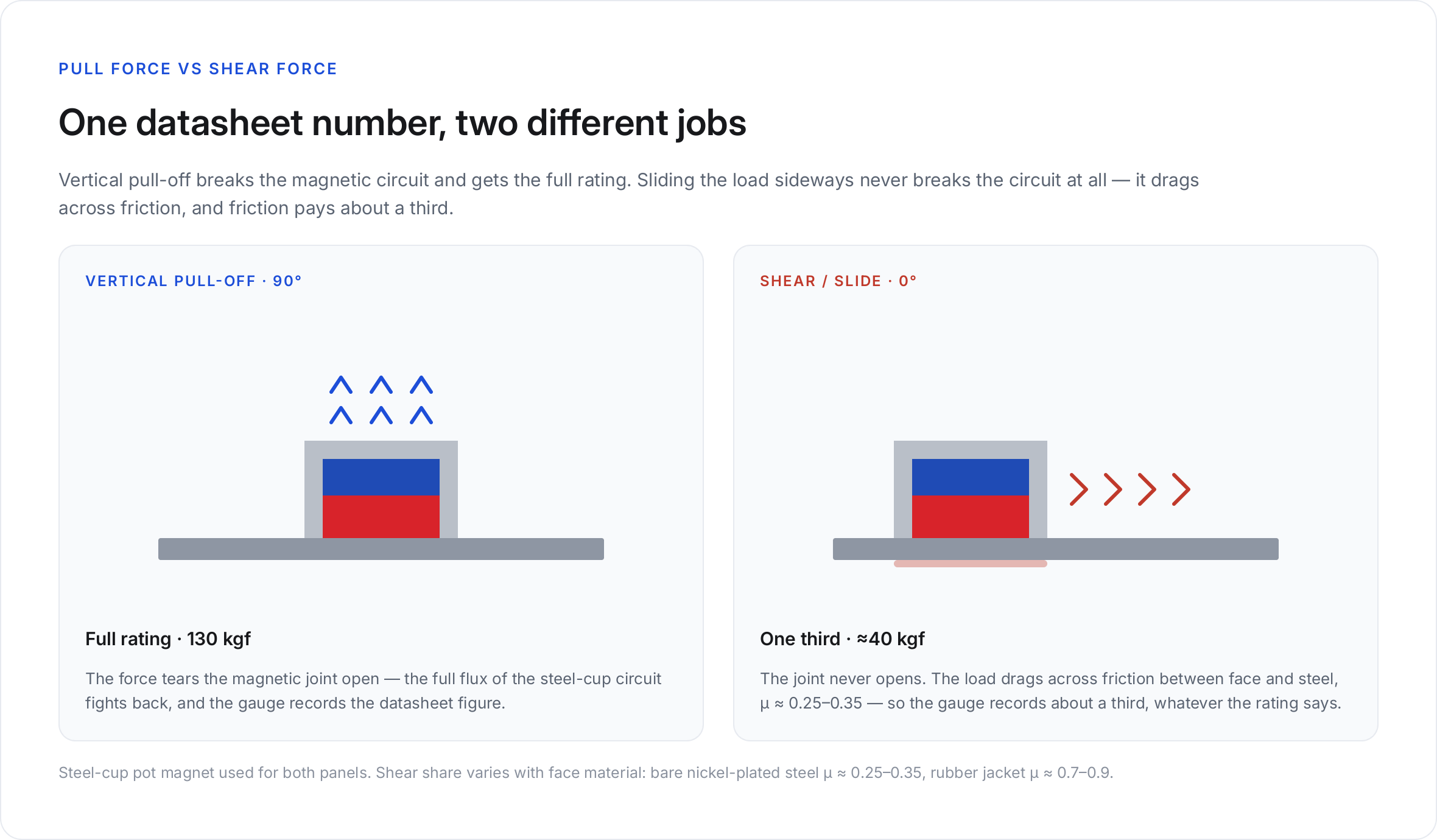
The single most common mismatch between datasheet and reality is direction. Pull the magnet straight off and you fight the full magnetic circuit. Slide it sideways and you are no longer breaking the magnetic joint at all — you are dragging it, and dragging is governed by friction, not by magnetism. No datasheet prints this second number, which is why every buyer needs the neodymium magnet pull force table below memorized in ratio form:
| Loading direction | What resists the load | Typical share of rated pull force |
|---|---|---|
| Vertical pull-off (90°) | The magnetic circuit itself | 100 % — the datasheet number |
| Shear / slide (0°, parallel) | Friction between magnet face and steel | ~25–35 % |
| Pull at 45° | A mix, dominated by shear once the angle tips | ~30–50 % |
(Infographic placement: vertical pull vs shear diagram, 46-pull-vs-shear-force.png)
The working rule is the one-third rule: a magnet's safe shear capacity is roughly one third of its rated neodymium magnet pull force. A 130 kgf pot magnet holds about 40 kgf when the load slides. A 25 kgf fishing magnet holds about 8 kgf when the rope pulls at an angle. Buyers who discover this rule after purchasing consistently size magnets as if the vertical number applied everywhere — and then report that the magnet "slides off a vertical wall with almost nothing on it". It does, and it was never specified to do otherwise. Memorize the ratio, not the number: whatever neodymium magnet pull force figure you are holding in your head right now, divide it by three and that is what the joint gets sideways.
The physics is ordinary friction — the same friction that governs a car tyre on a road. Sliding a loaded magnet sideways requires overcoming the friction force μ × N, where N is the normal clamping force — which, for a magnet stuck to steel, is approximately the magnet's own pull-off force — and μ is the coefficient of friction between the two surfaces. Polished steel on nickel-plated steel gives μ ≈ 0.25–0.35. So, for any neodymium magnet pull force rating:
Shear capacity ≈ μ × pull force ≈ 0.25–0.35 × rated pull.
Two consequences follow. First, the one-third rule is not a safety derating invented by cautious engineers — it is friction arithmetic, and it applies to every magnet shape from a neodymium magnet disc to a steel-cup assembly. Second, μ is the only lever you control: a rubber-jacketed magnet raises μ dramatically (rubber on steel ≈ 0.7–0.9), which is precisely why rubber-coated pot magnets are the specified answer for sliding loads and vibrating equipment — they trade peak pull for two-to-three times the shear grip and the friction to match. Nothing else in a holding system changes the link between neodymium magnet pull force and shear capacity as much as that face material does.
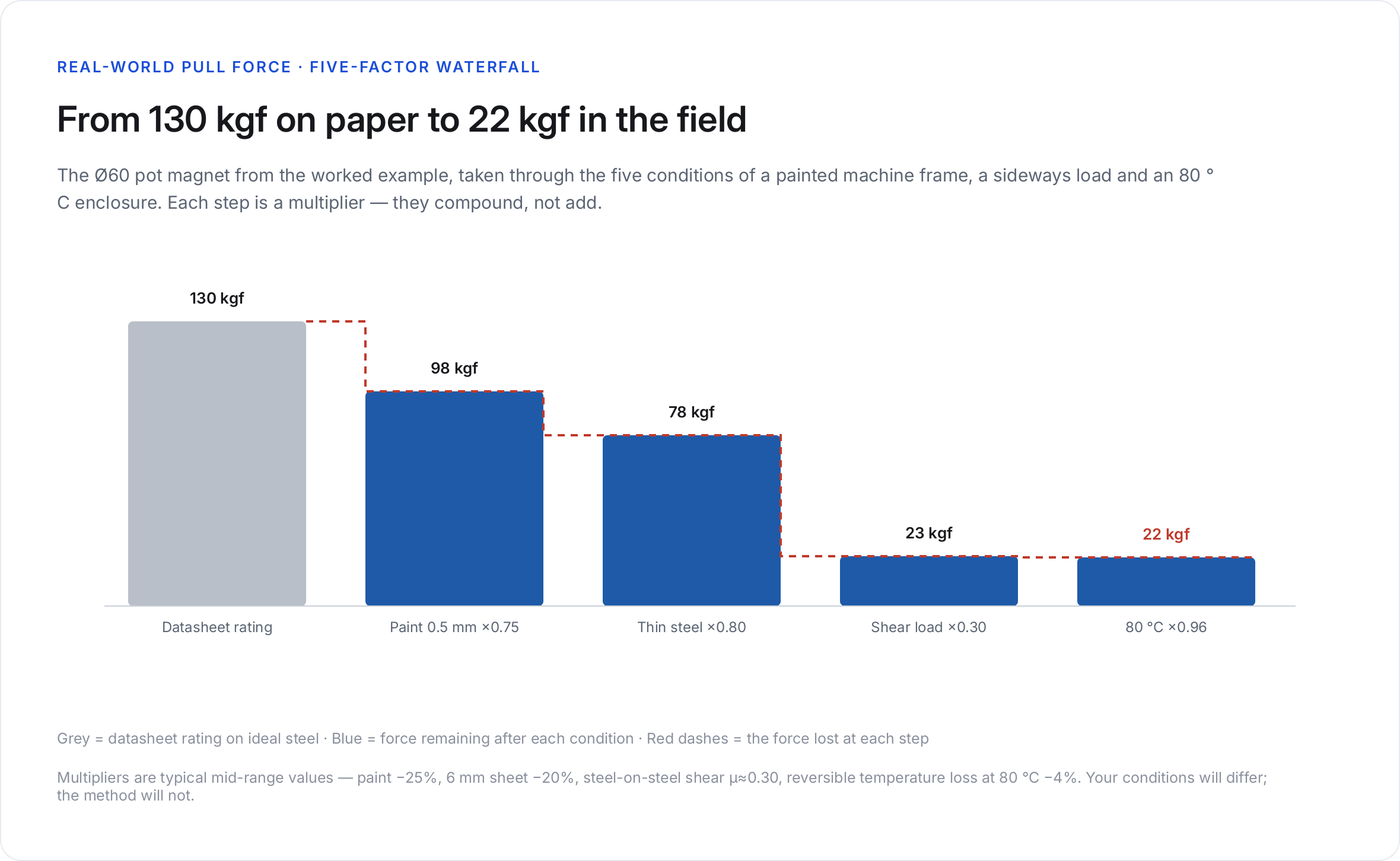
Between the datasheet figure and the force your assembly delivers stand five factors. Each one is a multiplier, and the honest real-world number is the datasheet figure multiplied by all five — the reason any quoted neodymium magnet pull force should be read as a starting point, never as a promise:
Factor 1 — Steel thickness. The magnet's field saturates thin steel quickly. A magnet that pulls 100 kgf on 20 mm plate may deliver 60–70 % of that on 3 mm sheet, because the sheet cannot carry all the flux and the excess leaks away as stray field — a thickness penalty no neodymium magnet pull force datasheet prints on the front page. The fix is not a bigger magnet; it is either thicker steel behind the magnet or a pot magnet whose cup completes the circuit internally. For the same reason the surface area matters: a Ø120 face on a small target closes a small circuit and wastes its field — the target-matching rule our single-sided fishing magnet guide covers with real size data.
Factor 2 — Air gap and surface condition. Anything between the magnet face and the steel steals force, and the theft is steepest in the first millimetre. Paint or powder coat: −20 to −50 %. Rust scale: −30 to −50 %. Silt or mud: −20 to −60 %. A millimetre of air more than halves a short-range circuit. Wiping the face between lifts — one habit, two seconds — recovers more force than any upgrade on the shopping list.
Factor 3 — Pull direction. The one-third rule above. Design the bracket so the load pulls along the magnet axis; if the duty is inherently sideways, specify for shear from the start and buy the magnet that carries a third of the job, not the whole one. Rating a sideways joint by vertical neodymium magnet pull force is the error this whole page exists to prevent.
Factor 4 — Geometry and the return path. Pull force scales with the magnetic circuit, not just the magnet. A long thin disc has a weak load line and demagnetizes itself against its own demagnetizing field; a short fat disc or a steel-cup assembly presents a stiff circuit and holds its rated figure more reliably. Length-to-diameter ratio of roughly 0.5 or more keeps a bare disc honest; below that, put it in steel — the shape decision matters as much as the neodymium magnet pull force grade printed on the box.
Factor 5 — Temperature. Remanence falls at ~0.11 %/°C, reversibly — about 9 % down at 100 °C — and past the grade limit the loss becomes permanent. The full grade ladder from N at 80 °C to TH at 230 °C is mapped in our neodymium magnet temperature guide. Any neodymium magnet pull force figure quoted without a temperature is a 20 °C figure, and a magnet specified for a warm enclosure should be re-checked against that ladder before the order goes out.
Here is the five-factor arithmetic applied to the Ø60 pot magnet from our range — rated 130 kgf on the datasheet — in a realistic duty: holding a steel bracket to a painted machine frame, load mostly sideways, assembly running at 80 °C. The point of the exercise is not the specific product; it is that a neodymium magnet pull force rating turns into a field figure through exactly this kind of chain:
| Step | Condition | Multiplier | Running total |
|---|---|---|---|
| Datasheet rating | vertical, bare thick steel | 1.00 | 130 kgf |
| Factor 2 | 0.5 mm paint on the frame | ×0.75 | 98 kgf |
| Factor 1 | 6 mm frame steel (thin) | ×0.80 | 78 kgf |
| Factor 3 | shear load, μ ≈ 0.30 | ×0.30 | 23 kgf |
| Factor 5 | 80 °C, reversible loss | ×0.96 | 22 kgf |
(Infographic placement: five-factor derating waterfall, 47-pull-force-derating.png)
22 kgf of honest shear holding from a magnet labelled 130 kgf. Nothing failed; every clause of the datasheet's fine print simply applied. This is why responsible sizing inverts the question: start from the load the joint must carry in its worst direction, divide by the multipliers, and then read the datasheet — that inversion is the only reliable way to use a neodymium magnet pull force number. A joint carrying 25 kgf in shear needs roughly an 80 kgf-rated magnet on that painted thin frame — the Ø60 in this example lands almost exactly there once a modest safety margin is added.
The lab figure comes from a pull-test rig: the magnet fixed to a force gauge, drawn vertically off a certified steel block until separation, peak recorded. Reputable suppliers measure at breakaway — the peak — because holding force decays slightly as the magnet tips away from the surface. This is also why our product pages quote a single number per size, measured identically across the range: the magnetic hooks family from 1.2 to 250 kgf, the fishing magnets from 4.5 to 480 kgf, and the pot magnet range are all directly comparable because they were tested the same way. When two catalogues disagree about the same part, it is almost never the magnet — it is the neodymium magnet pull force test conditions behind each number.
What the rig does not test is your steel, your paint, your angle or your temperature. Those are your multipliers — which is the entire content of this guide, and the reason two buyers can hold two different magnets under two different numbers while quoting the same neodymium magnet pull force datasheet.
Once the multipliers are applied, the residual number should still not be the working load. The gap between calculated neodymium magnet pull force and the force you can trust is covered by three reasons that stack up:
The working rule across industry: static holding applications get a 3× margin on the calculated real force, human-adjacent or dynamic applications 5×. A neodymium magnet pull force figure with no margin built on top of it is, by definition, one surprise away from letting go.
Bigger diameter is the expensive answer. Four cheaper ones usually move the real number further — and each of them attacks a different factor, which is why they add up faster than the neodymium magnet pull force scale itself does:
If after these four the joint still runs short, then the diameter goes up — and when the application is genuinely new, the fastest route is to send the joint's drawing, load direction and environment through the custom magnets page rather than over-size and re-engineer later.
Because every catalogue figure in our range is measured the same way, the one-third rule and the five factors translate between families unchanged — one neodymium magnet pull force measurement convention across the whole catalogue:
| Family | Rated pull (range) | Honest shear (one-third) | Where the family wins |
|---|---|---|---|
| Pot magnets | 5–500 kgf | 1.5–170 kgf | Stiff steel cup, thickest circuits, best force per gram |
| Magnetic hooks | 1.2–250 kgf | 0.4–85 kgf | Load hangs on the fitting — pull direction is native |
| Fishing magnets | 4.5–480 kgf | 1.5–160 kgf | Rope-borne dynamic loads, eyebolt interfaces |
| Rubber-coated magnets | 7–150 kgf | 5–105 kgf | μ ≈ 0.8 — the shear specialists |
Note the trade the last row makes: less headline force, far more grip. It mirrors the energy-versus-toughness trade in the grade comparison — every holding decision is an exchange, and the datasheet's headline column is only ever one side of it.
Read the shear column before the pull column when the duty involves walls, vibration or sideways drag — that is the column your joint actually lives in. And when a catalogue figure looks implausibly high, check that the conditions match ours before comparing neodymium magnet pull force numbers across suppliers.
Q1: What does pull force mean on a neodymium magnet? A: It is the force needed to pull the magnet straight off (vertically, at 90°) from thick, bare, flat steel with full contact. The neodymium magnet pull force figure is a lab measurement under those four ideal conditions — not a general "strength".
Q2: Is pull force the weight the magnet can lift? A: Only when lifting straight up off clean thick steel. In shear the magnet holds roughly one third of the rated figure, and any air gap, thin steel or heat reduces it further — the rated neodymium magnet pull force is a ceiling, not a daily figure.
Q3: Why does a magnet hold less when the load slides sideways? A: Sliding does not break the magnetic joint — it drags across it, resisted only by friction between the magnet face and the steel. With μ ≈ 0.25–0.35 for steel-on-steel, shear capacity works out to about one third of the rated pull force.
Q4: How much pull force do I lose through paint or rust? A: Expect −20 to −50 % for paint or powder coat and −30 to −50 % for rust scale, depending on thickness. The loss concentrates in the first millimetre of gap — clean metal contact recovers most of it.
Q5: Does a bigger magnet always hold more? A: On the same conditions, yes — pull force scales with the magnetic circuit. But against the five factors, a smaller magnet on clean thick steel with an axial load can outperform a bigger one on painted thin sheet in shear. Compare candidates at equal conditions, then let the application pick the winner.
Q6: What is a safe margin when sizing a magnet by pull force? A: Apply the condition multipliers first (surface, thickness, direction, temperature), then keep a 3× margin for static holding and 5× for dynamic or human-adjacent loads. A neodymium magnet pull force figure used with no margin built on top is one surprise from failure.
Q7: Which magnet shape gives the most pull force for its size? A: Steel-cup assemblies — pot magnets. The cup completes the magnetic circuit and typically multiplies the bare disc's pull by 3–8×, the largest single gain available at any given neodymium magnet pull force budget. See our pot magnet guide for the construction and the full range.
Q8: Does temperature change pull force? A: Yes, reversibly at about −0.11 %/°C — roughly 9 % lower at 100 °C — and permanently if the magnet passes its grade limit. The grade ladder is covered in our temperature guide.
Q9: Why do different suppliers quote different pull forces for similar magnets? A: Measurement conditions differ — steel thickness, surface finish and breakaway versus sustained readings all move the number. Ask what steel block the figure was measured on; if the answer is vague, treat the quoted neodymium magnet pull force as marketing rather than specification.
Q10: Can I calculate pull force from magnet properties alone? A: Not reliably. Pull force depends on the whole circuit — geometry, steel, contact — so datasheets come from measured breakaway tests, not from Br × area arithmetic. For engineered holding joints, send the load case to engineering; that calculation is exactly what the custom magnet service does.
The number on the datasheet is real — vertical, bare, thick, clean steel — and your application is none of those things. Neodymium magnet pull force in the field equals the datasheet figure multiplied by five honest factors: steel thickness, air gap, direction (the one-third shear rule), geometry, and temperature, with a 3–5× safety margin on top of whatever remains. Size the joint from the load case, not from the catalogue peak, and the magnet will do quietly for years what its label promised for one clean second in the lab. Send us your worst-case joint — direction, surface, temperature — through the custom magnets route or contact us directly, and the engineering team will return a sized recommendation with the test data behind it, shipped fast for U.S. buyers from our Redlands, California warehouse.